The Footer…
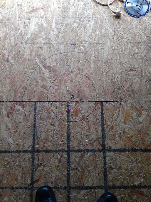
To find this center point I used a plumb bob and marked a spot on the floor directly under a reference point on the drive track inside edge. Knowing the diameter of the inside of the drive track was 87″, I found the opposing point 180* opposite, scribed a reference point there and again a mark on the floor. Next I measured from the reference points on the track down to the mark…each was 96″ in my case. The 96″ represents one leg of a right triangle. Next I drew a line connecting the 2 marks on the floor and put an ‘x’ at 1/2 the distance….43.5″ in my case. This 43.5″ represents the second leg of the triangle. With these 2 legs we can calculate the hypotenuse to be @ 105.5″. I cut 4 strings to this length and taped one end of each at the 0/90/180/270* points on the track. I pulled the other end of the stings down to the floor, and where all 4 met, marked the point….which was essentially at the x previously marked. Lastly we drilled a hole marking the final position.
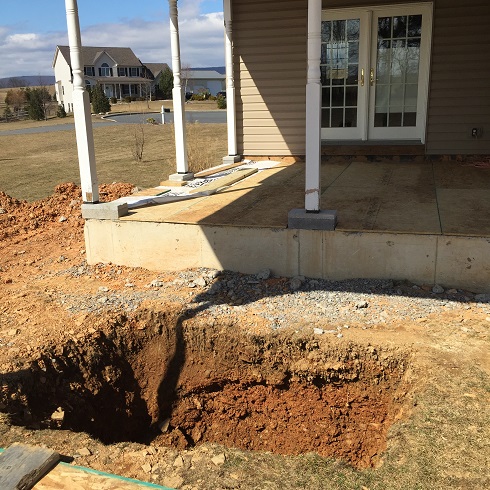
Once dug out, I again dropped the plumb-bob to mark the center of the footer at the base of the 4x4x4 hole. Here I drove a piece of rebar. The overall footing plug is 4x4x5 deep since I extended it about 12″ above grade. Next I measured out from the centered rebar stake for the corners….34″ radially from center to be exact. To assure the footing was square with the house I remeasured the baseline and used a plumb bob to transition the ends of that line to the bottom of the hole. Then I measured between each corner point to assure 48″ (the perimeter of the box). Lastly I verified 2 separate lines between two corner points (that went across the middle) were equal. I drove corner stakes at the final positions of the 4 corner points to finalize the footer footprint. I severely underestimated the work to prep the footing for the pour. Dig a hole and fill it with concrete right? Not quite. I wanted to raise the footing 16″ out of the ground so I would need less (of the more unstable) pier above it. This meant I would need to build a wooden form above the ground to hold that concrete. Other complicators were the un-level ground surface and the fact my hole was way overdug by the excavator requiring special bracing to assure that side didn’t blowout during the pour. The rebar cage was a challenge too. Following are the detailed steps.
To start I cut 2 sheets of plywood in half (for 4×4 sections) to make the walls of the footing. I dropped each section into the hole and attached them outside their corner stakes with some 2x scraps and screws. Inside of each corner on the ground I placed a solid 16x8x4″ concrete bock. These blocks will support the corner posts of the rebar box. Rebar shouldn’t be in contact with earth at any point. When there is contact, rust will start at that end and eventually rust the entire piece out. It will also likely spread to other bars in contact with it. You will end up with large long voids in the concrete that rebar previously occupied. I make sure to leave at least 2″ between metal and dirt at all points.
The rebar box starts with 1/2″ (#4) rebar stood-up vertically 2″ inside of each corner. Rebar is easily cut with a circular saw and an abrasive blade. After making sure each bar was plumb, I attached the tops to the plywood box to keep them in place….a 3/4″ hole in a scrap of plywood is a great jig for this task. After all 4 were up, I built the first of 4 rebar “floors”. Each floor is 7 rebars laid in parallel, horizontally and evenly spaced. These 7 bars are supported on each end by a perpendicular bar…so each floor is 9 bars total. The end of every bar is tied with 17 gauge fixing wire to the one it crosses. All floors are level and roughly 12″ apart. The first floor was just a few inches above the bottom of the footing hole and the last one landed a few inches above it.
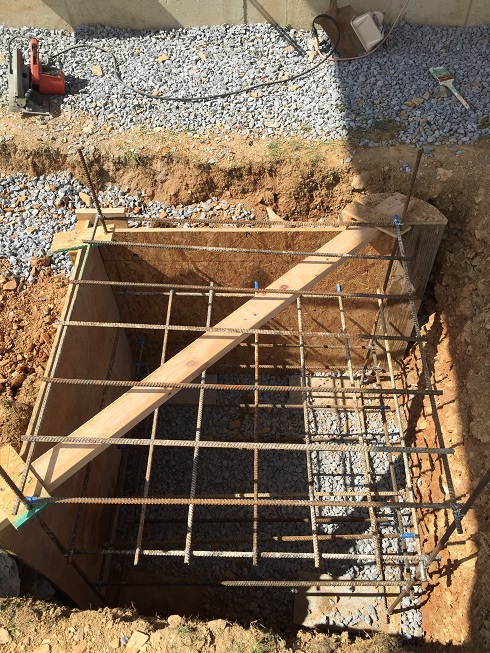
After all the rebar was placed I started on the above grade form. The box was basic…4 48″ 2x12s screwed together at their ends to make a 12″ high square. If the grade was level I would be mostly done….but it was not….so I had to lay 2x12s flat on the ground around the perimeter of the hole. Then 3/4″ holes were drilled into the ends of these boards and rebar driven though and into the ground to keep them in place. The box built previously was placed on this 2×12 base and was obviously far from level. The edge opposite the highest edge was build up by placing additional 2x12s until reaching level all the way across. The sides were then filled in with scrap plywood & 2x to seal all possible gaps assuring there would be no escaping concrete. I then back filled the form in the hole with dirt and placed a 3/4″ plywood cap on top. I also threw some crushed stone in the bottom of the hole for good measure. This will assist with drainage.
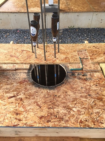
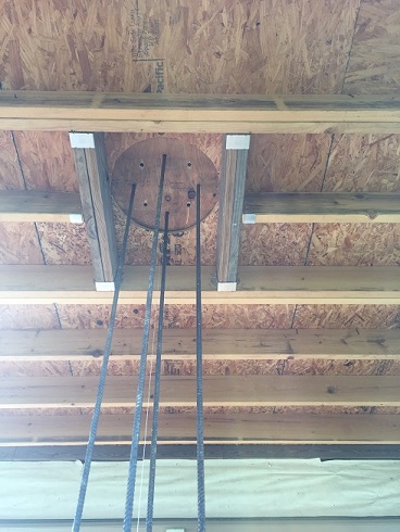
Next step in the footing work was to build a base for the pier’s rebar cage. This was a 12″ diameter vertical rebar tube comprised of 4 vertical bars connected horizontally with 12″ diameter rebar rings. 4 – 72″ bars were cut for this pier base. I took each one, placed it in my trailer hitch receiver, and bent a smooth 45* arc at one end. This will give the pier base structure much more stability as it runs at an angles through the footing. I next found the exact center of the plywood footing cap and scribed a 16″ circle around it and cut it out. 16″ is the diameter of the pier. I then fabricated a ‘reber jig’ at the top of the footer about a foot above the 16″ cut out. On this jig I marked all 4 of the 90* intersections to the circle and then measured in 2″ from each point and drilled a 3/4″ hole. Each of the 4 rebars were fed through these jig holes with 24″ remaining above it. Each bar was leveled and the lower ends wire tied to the footing cage bars. The holes in the jig (that the bars were fed though) kept them secure and in place.
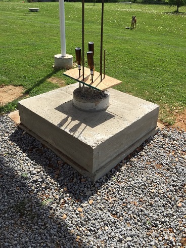
4 more holes were then drilled into the jig between the others an full size bars (16′) were fed down though it that extended up to the observatory floor. Again these were bent at angles at the bottom and tied into the footer rebar cage. These 4 bars extended all the way down and sat on the the footer blocks

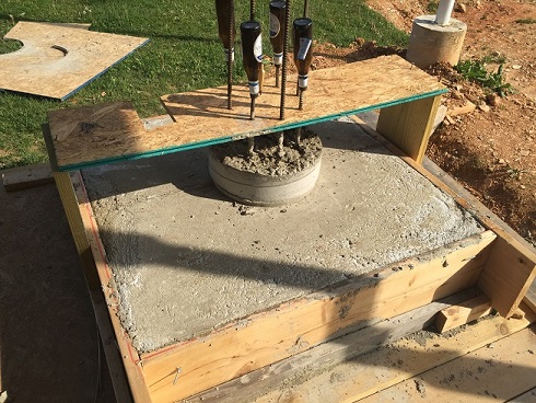
The final task was to cut 6″ off the cardboard sonotube to be used as a kicker form. This 6″ ‘ring’ was placed on top of the footer and will be filled during the footer pour. later, the pier sonotube will actually slide down over this dry kicker plug when it is being placed.