The Plan…
Conceptualization for AI2 started in December 2013 and construction of Station 1 completed 22 months later. Another 6 months of work inside and first light was April 2016. The planning took over a year to get right. The actual construction (building) took only a 3 months. Planning should always be 90% of the time for project like this. Initial planning took the form of pen to paper and later graduated to Google SketchUp to render a 3D CAD model.
A thorough understanding of modern construction techniques is necessary to build to the tolerances required for this type of project. If you do not possess such skills then plan on outsourcing those bits of work or you will likely be unsuccessful. While the internet is an indespensable reference, it is no substitute for an experienced carpenter. This blog isn’t meant to be a ‘how to’ guide by any means but rather a detailed account of one way to do it.
- In the following section I will share some early points of considerations that will help steer you to the optimal design based on the scientific goals you are pursuing
- What types of research will be conducted and what are the research objectives and goals? Most mid- sized (3-6 meter) dome observatories can adequetly handle the common instrumentation for Spectroscopy, Astrometry, Photometry and Astrophotography (Solar system and deep sky). Remotely controlled (robotic) telescopes are also a very popular income stream for an observatory but competition is steep as are the start-up costs and technical challenges.
- Where will the observatory be located? Typically the dark, still skies that make for research grade astronomy are far from where most of us live. You should have a good understanding of the sky quality overhead at the site you are planning as well as the limitations it presents. While filters, adaptive optics and other special technologies can reduce light pollution and certain atmospheric conditions, there will always be limitations in most suburban and even rural areas. Have a look at the following links (link to Bortle, Danko, Google dark sky proj) and be familiar with astronomical ‘seeing’. Weather trends are also worth knowing. Yuma AZ has an average of over 300 clear nights a year while Portland, OR has about 155. So you can potentially do 2x more Astronomy in Yuma! Also be aware of overhead air traffic which will smear your data. Finally its worth thinking about the area of the sky you will be able to access from your latitude. From the north pole only 1/2 of the sky will ever be available to you. As you move further south more comes into view. At the equator all of the sections of the sky come into view throughout the year.
- How high off the ground can the telescope instrumentation be placed? At higher elevations, the atmosphere is thinner thereby minimizing the effects of atmospheric turbulence and resulting in better “seeing”. There are two main components to this turbulence:
- Low-level terrain disturbance. This results from the surrounding topography. For instance, valleys are filled with colder air during the night, resulting in greater thermal differential vs ground and therefore more intense low-level turbulence. Hillsides, hilltops and bottoms often have more unsteady air as well, mostly due to the constantly sinking cooler air around them.
- Local air turbulence is produced as objects and surfaces warmer than air (like pavement, roofs, roads, you! [a person at rest dissipates around 200 watts]) raise the temperature of the air layer around them, causing it to rise up forming turbulent, non-uniform light-transmitting structures.
To mitigate these air effects it is highly recommended to get the pier up as high as possible. This is the main reason most professional observatories are located on mountain tops.
- What size pier will be needed? Mid-sized observatories generally have piers ranging from 8″ diameter and 3′ high to 24″ diameter and 20′ high. The pier will be the most important element of the design if any meaningful research is expected to take place. For support, a below grade footing will be placed and this becomes significantly more massive as the pier diameter and/or height increases. The pier must also be completely isolated from the observatory floor to assure vibration isolation between the observatory structure and building machinery. The pier height is relative to the dome horizon line and should be set to allow an unobstructed telescopic view starting from about 10 degrees above earth’s horizon. A rule of thumb is that the RA/DEC axis of the mount should fall slightly above the shutter sill. Be sure ALL footing/pier placements consider the true azimuth line and NS cardinal points. Piers are generally poured concrete that can be hollowed out to reduce the moment of inertia and the thermal mass issues. Deflection is another major concern with the pier and can be calculated using deflection formulas found here. A mounting plate will also be required to transition from the concrete to the mount base.
- Where will the control room be located? The temperature and humidity inside the observatory dome MUST be equivalent to (or less than) the ambient temperature outside the dome. This requires minimum heat generation, good ventilation, no insulation, and a low thermal mass construction. There are many reasons for this, most important of which are
- Light gathering instrumentation needs to be very cool to operate effectively. Most obvious is the CCD imaging chip. A heated room will work in opposition to this.
- When the dome shutter opens, if the air entering is not at equilibrium, scope mirrors will warp and distort images at the focal plane.
- Telescope dewing will also result from warmer air inside tube depending on the humidity
- Telescope flexure (especially if synchronized optics are in use) is another optical pitfall that occurs when there are temperature differentials
For these reasons there needs to be a separate, but typically adjacent, room to operate the observatory’s main systems. Typically a space the size of a small bedroom would be plenty to house the main instrument controls for configuration, run, acquire and process. Always maintain a close proximity to the dome….do not exceed 125 cable feet of the telescope pier. An area for making coffee and a spot for short naps will make you much more productive across a session. The control room should be in the initial planning as data and electrical conduits will need to be installed. Where possible, utilize ventilation systems to exhaust heat downwind from the dome.
- How often will observing sessions take place and what will be the typical duration? More frequent observing demands certain types of physical automation like:
- Dome rotation
- Powered shutters
- Actuators/motors/controllers/sensors/switches/etc
And if observing remotely:
- Firewalls/VPN for remote logon
- System redundancy and failover protections
- Survalience
- Weather monitoring
- I start observatory designs on paper with freehand sketches to get ideas on the possibilities for placement, framing options, view obstructions etc. I had a total of 4 design considerations for Station 1 but settled on the extended roof for many reasons. Being attached to the house has big advantages in access, security, electrical/network wire runs. However, such a design required signoff from others with stake in the house…namely my wife. After long discussions she was willing to go with the plan under the following conditions:
- The entire structure must be easily removed if/when the time comes. Once removed the house must be easily returned to its original condition. I took ‘easily’ to mean @ 1 days work. This also gives potential future home buyers the option to keep it or not….preserving our ability to sell without obstacles if we ever need to.
- The final construction must have ‘very little’ impact on the outdoor experience. In other words it should blend with the rest of the house and not be an eyesore. It also shouldn’t detract from the views. Obviously this is all a bit subjective (I think it’s beautiful). But so far it hasn’t offended anyone.
Specific to the marital terms, the entire structure is removable by pulling a handful of nails and replacing some soffit, corner returns and vinyl siding. This ‘undo’ feature required some additional modern building hardware and fabrication techniques. To keep the eyesore factor low was mostly achieved by continuing the existing roof line and matching posts, shingles and other siding elements.
While these conditions certainly presented some challenges, there were a few other, more difficult, ones to tackle. When extending off any habitable structure you need to plan for wind dynamics, complex air currents, heat flows and the heat sink effect, vibration transfer etc…..issues not so important when building detached.
The other challenges were largely addressed by locating the observatory instruments ~20′ off the ground and ~21 feet from the nearest heated wall. Fortunately the wind and heat sink issues are intermittent and can be planned around.
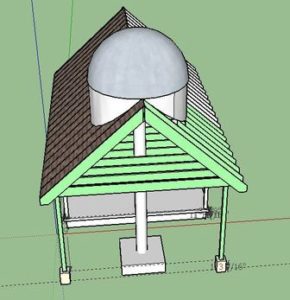
- After the final concepts were penciled out and it seemed plausible, the layout entered the next phase….modeling in SketchUp. Google Sketchup is a remarkable little bit of software. It’s very intuitive and sits on a huge knowledge base. The simplest way to explain it (if you aren’t familiar with CAD programs) is that it’s like a digital Lego set. Using basic shapes you can build anything from a simple one color, one texture ball to the strikingly complex. I have seen models of Apache helicopters, F1 racecars, the Colosseum of Rome and even a full scale metropolis! And these aren’t ‘outlines’ or artistic renderings, these are full scale, entirely zoomable, all parts inclusive, user intractable, 3D experience of the object(s) of interest. Once a construction design is complete you can easily export plans for permits, supply takeoffs or exterior elevations….and show for each phase. You can do a virtual ‘walk-through’ and save layers for each part of the build to present a movie-like demonstration of the project start to finish. The platform makes heavy use of artificial intelligence (sometimes to where it’s scary) and can often predict what you want to do and do it for you! There are also numerous libraries, consisting of objects and builds from other users, that you can easily import saving you lots of time. Best of all, the freeware version will likely meet all your needs.
Reference websites, books, etc here