The Pier…
By far the most stressful part of the job was the pier. Standing up 1 ton of concrete vertically with the exacting specifications demanded by astronomy gave many opportunities for error….an if an error should arise then what? Check the astro forums and you’ll find examples where piers needed to be jackhammered out and replaced! I had no appetite or fortitude for such a task. So with the goal clearly set, a one-time pier install, I got started.
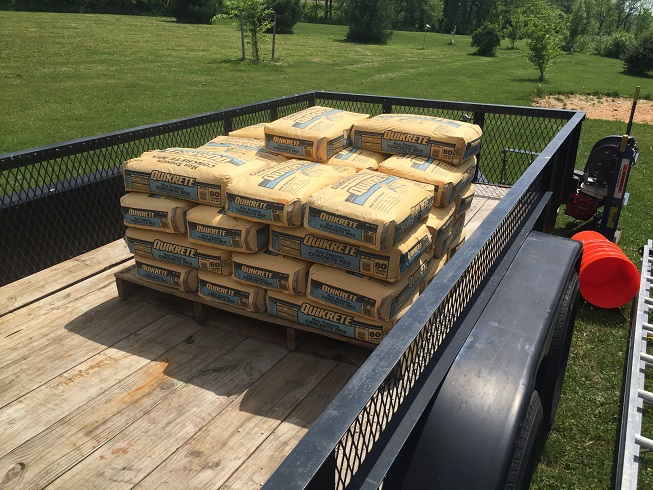
- The project starts a couple weeks after the footer is poured to allow a little hardening time there. The plan called for 26 – 80lb bags of 4k PSI concrete. I would again need to vibrate it in during the pour so I rented that again. Since the top of the tube would be about 12′ from the ground I was forced to mix by hand as there were no pump trucks in the area…and to bring one in would cost a hefty sum. This also worried me a little since mixing by hand can result in too much water being added weakening the pier. The water would need to be carefully rationed during the mix. Two more critical items were the mixer and the hoist ladder. With everything on site the hard work starts.
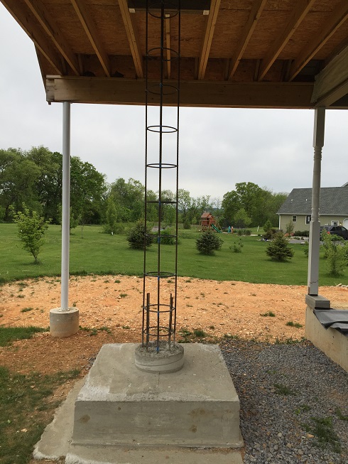
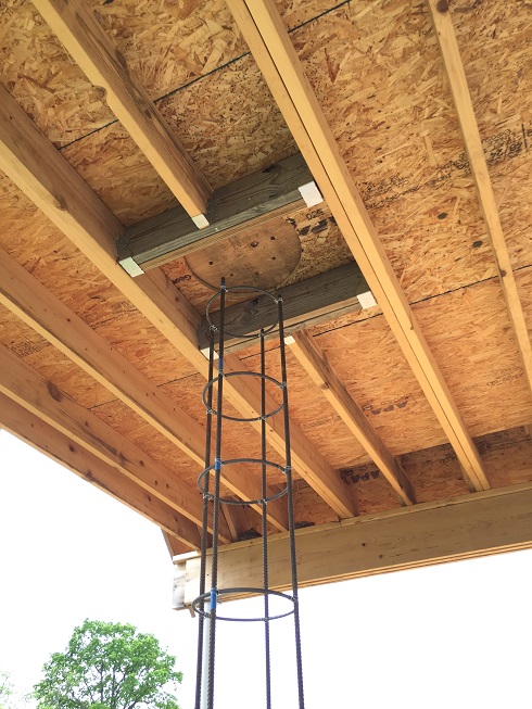
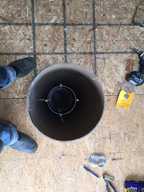
- I cut down the tops of the vertical rebars 12″ below the observatory floor. Next I wired in the rings form the bottom up every 12″ to the top. The rings were 11″ diameter rebar straights that I had rolled by a local manufacturer. After everything was tied together I was surprised VERY rigid the rebar cage was without any support above the base….even with a good ‘jostle’ it didn’t budge at all.
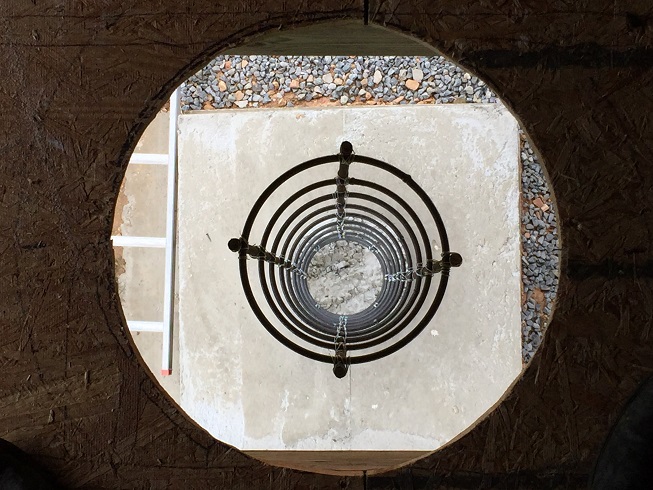
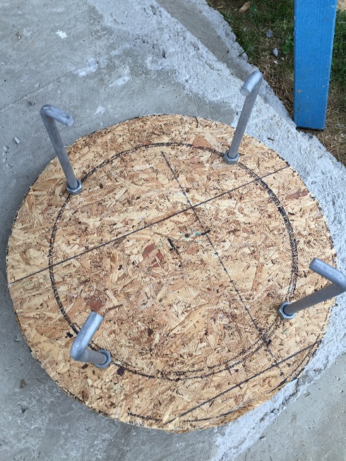
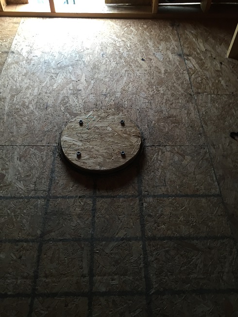
- At this point I put together the jig for the Jbolts. This was two 16″ plywood disks drilled out for the 4 evenly spaced Jbolts. I positioned my Jbolts 2″ in from the outside of the pier and I used 1/2″ x 10″ Jbolts. A good idea here was to dill the hole though both disks at the same time so the Jbolts sat exactly vertical when inserted. Once inserted I put nuts on both sides of the lower disk and then one on top to lock it all together.
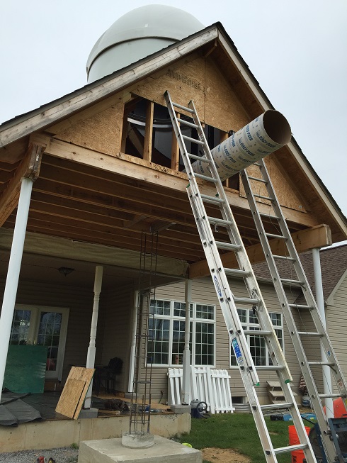
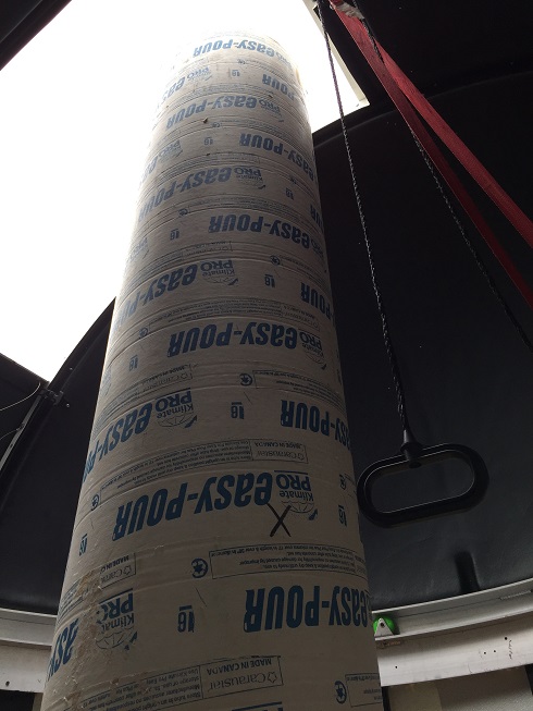
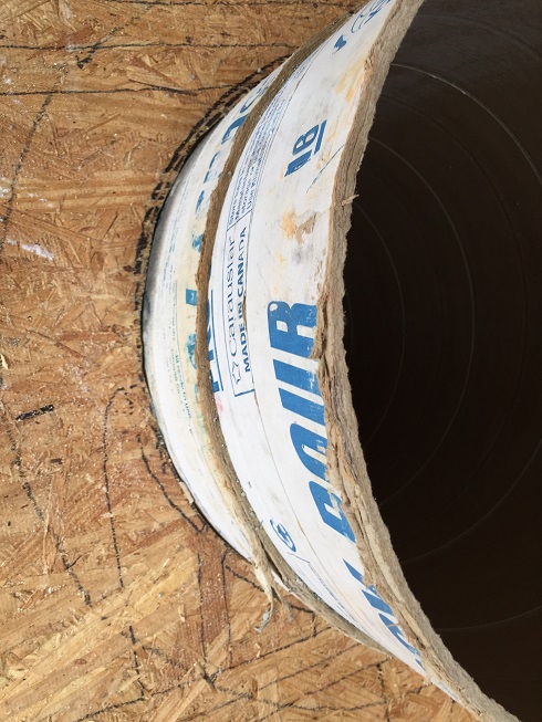
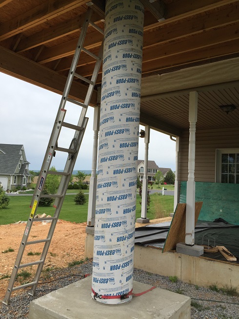
- Now it’s time to drop the sonotube down over the rebar cage. I used a 12′ Easy Pour cardboard form tube that was a stock item at my local concrete supply house. It’s a commercial product that is much thicker than anything the home improvement box stores will carry. With the dome already installed, getting this into place was a little tricky. Since my gable end wasn’t sided yet, I pulled off a piece of the plywood there, chopped out a stud, pushed the tube up a ladder and into the observatory. From here I just opened the dome shutter, stood the tube up into it and then I was able to swing the bottom into the hole and down over the rebar. Finally, something that went EASIER than expected. Not much of that in this project. I then drilled two tiny holes in the sonotube and inserted wire to keep the rebar cage centered. I also took the 6″ kicker cutoff and wedged it between the tube and the floor to assure the tube was centered in the hole. Lastly, to minimize the risk of a blowout at the base, I strapped a tiedown around the bottom of the tube sucking it in nicely to the kicker.
- Next was the concrete. I mixed one bag at a time adding 4 quarts of water to each via electric mixer. After it was uniformly blended I poured it out of the mixer and into a 5 gal bucket. I put that bucket on the hoist ladder and hoisted it up to the observatory. I then climbed the adjacent ladder, swung the bucket into the observatory and poured it down the tube. 26 cycles later and the pier was poured. It’s critical to mention that with each bucket I ran the vibrator all around the tube (outside and inside the rebar cage) and down into the pervious pour. There certainly were air pockets forming due to the dryness of the mix and the amount of rebar but the vibrator made all the concrete settle nice and smooth. Once the pour was up to floor, I dropped the Jbolt jig on top, checked the tube was level and called it a day.
- The 16″ concrete pier terminates at the observatory floor. Atop the concrete pier is a 6″ diameter steel DOM (1/4″ wall) pipe that runs up to the dome equator where it marries the mount. I ran a two piece pier for a few reasons:
- If I want/need to break-down the observatory, I can topple the pier w/o any deconstruction of the framing or the roof. For example, if I ever sell the house.
To convert the observatory to a normal roof would only require three steps:
- Drop the pier
- remove the cylinder dome support and dome
- Plywood over the opening and paper/shingle it (I ordered extra shingles for just this purpose)
- A 16″ diameter at the mount would increase the risk of equipment collision
- Lowering the scope (if I ever had to) would require chiseling concrete….not something easily done…and any dust would certainly find its way into the delicate optics and electronics nearby. Any raising of the scope would best be done with steel…so why not just run all the way up from the floor?
- If a piertech or other pier diameter/composition/function should be required, it’s easy to swap out the top section for modification.
In short, a removable top section maximizes flexibility for future changes.
- The specs for the steel pier fabrication are outlined here. As described above there were four 1/2″ j-bolts sunk into the head of the concrete pier and “dried in place” Those jbolts rise up into a 3/4″ thick steel disk that is the same diameter as the pier (16″). Threading a nut and washer down each jbolt holds the disk securely in place onto the concrete pier. Four 1/2″ bolts were welded into the disk that align with the flange on the base of the steel pier….these bolts are inside the jbolts. Threading a nut and washer down the flange bolts holds the steel pier securely in palce on the disk. Lastly, for the head of the pier I fabricated two 7″x7″ steel plates that were 1/2″ thick…one “upper” and one “lower”. These two plates were sandwiched together and joined the pier with the mount base.
- Lower. I welded this plate onto the top to the steel pier. The following holes wre drilled:
- Four 1/4″ holes….one in each corner to attach the upper plate (sandwich style)
- One 2″ hole in the center for the mount’s M12 center bolt to drop into (handle side)
- Upper. This plate was attached directly to the mount base. The following holes wre drilled:
- Four 1/4″ holes….one in each corner to attach the lower plate (sandwich style)
- One 12mm hole in the center for the mount’s M12 center bolt to pass though upwards and thread into the mount
- Two 8mm tapped holes for the mounts M8 azimuth bolts to bolt down into
- One post to act as the position pin on the South side of the plate (the azimuth screws push off this)